
The group assignment for this week has to cover the following.
We decided to look how power supply, multimeter, oscilloscope and logic analyzer work.
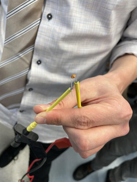
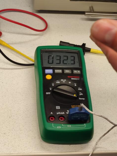
This is a test equipment we are most comfortable with. All of us use if fairly often, for example checking short circuit. However multimeter is a powerfull tool, and has many other use cases. We checked the voltage and current of a circuit (more on that in power supply section) and capacitance of a capacitor. Sometimes the components in lab can get misplaces, so it is advised to check their parameters before use.
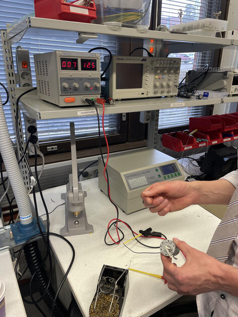
Suprisingly, multimeter can also measure the temperaure. We can see if the component is withing is rated working temperature, or of its overheating. On the picture we were measuring the temperature of Kris cold hands.
Power supply can create a specific voltage, and limit current to some maximum value.
Limit current:
Before you turn it on, you can connect the terminals. Then when you turn it on, the voltage will be 0 (as we just made a short circuit), and we can then set the maximum current that will be flowing.
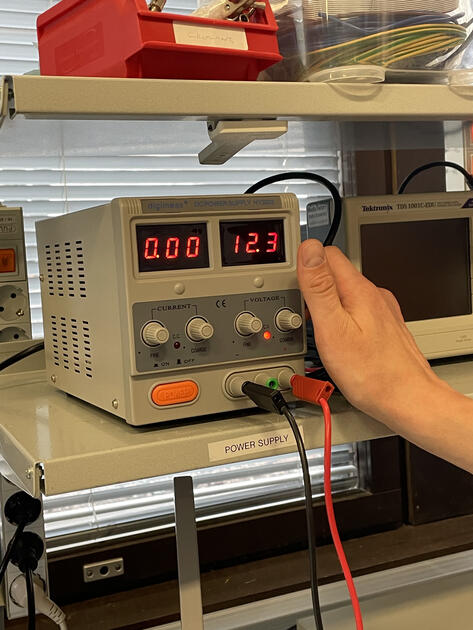
Set voltage:
After that we turn off the machine, and disconnect the terminals. Then, when we turn the power supply back ok, we can set the desired voltage. There are two knobs - coarse (bigger steps) and fine (for fine tuning).
I use power supply to test the motors, to see what is their working voltage and how much current they draw.
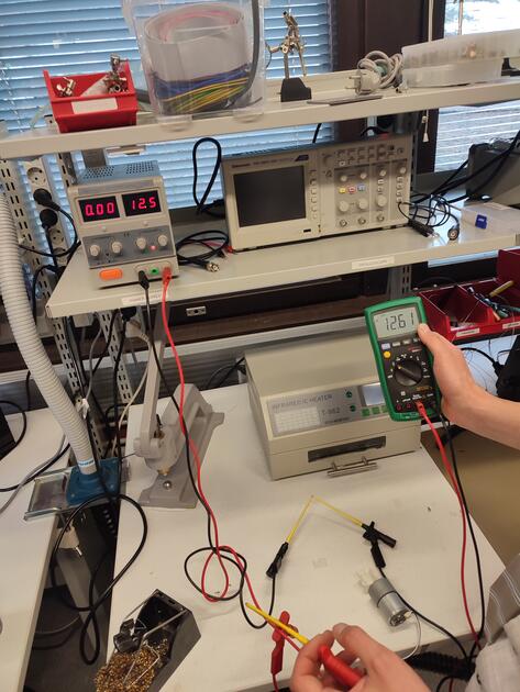
We then used the multimeter to check is the voltage and current is same as shown on power supply (as multimeter has a bit of better precision). We connected the multimeter in series with the motor.
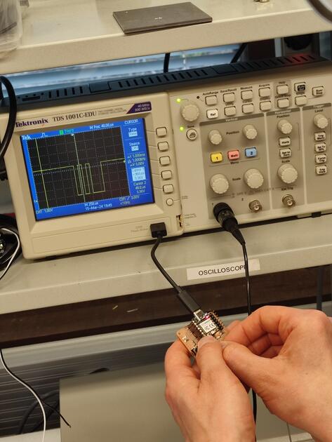
We can think of oscilloscope as a multimeter, but in time. It can draw the signal changes (voltage) in time, which can be sometime very useful to debug boards.
On the picture bellow is an oscilliscope. The screen is mostly yellow because we are too zoom out.
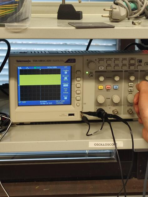
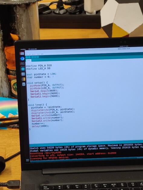
This is the board we were testing. It has an LED that is blinking every second, and it is also outputting an number through UART. We will try to see the changing numbers on the oscilliscope.

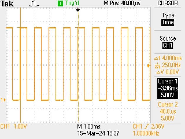
The LED is turning on and off, so we see a square wave.
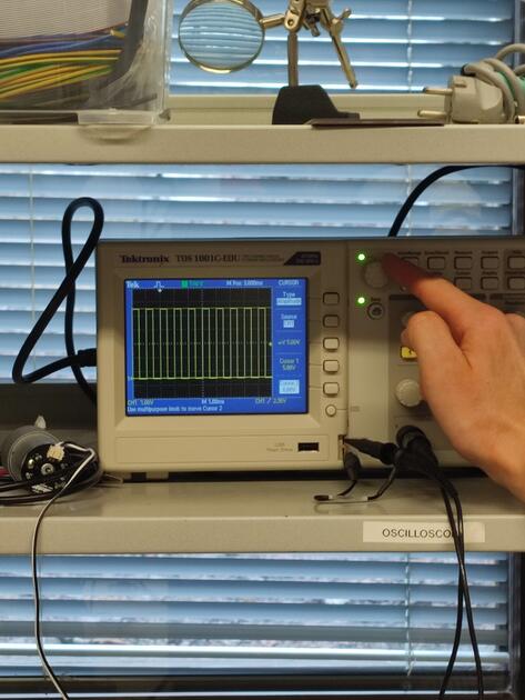
We were trying to see the changing numbers, but we were having some troubles understanding the routing, so at the beginning we directly connected the oscilloscope to TX pin on the microcontroller.
We can see the changing numbers!
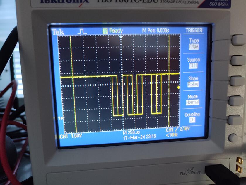
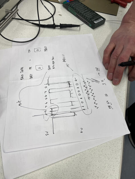
Kris explained to us that the numbers are encoded as an 8-bit binary number, and showed us how to translate that back to decimal number.
The oscilloscopein the lab can also take a screenshorts and store it in the USB stick. Cool!
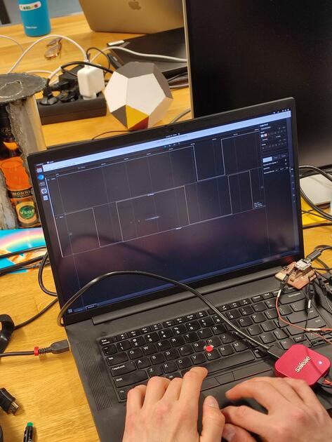
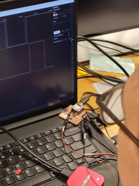
We have a Saleae logic analyser in the lab - the use case is similar to oscilloscope, but much more powerful and advanced.
The code on the boars:
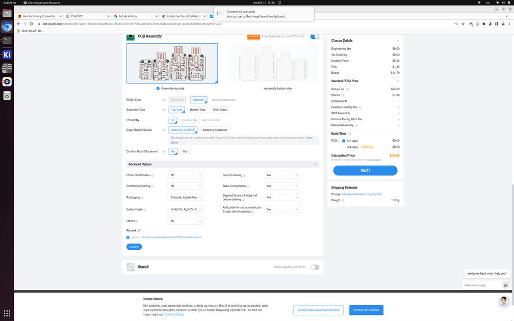
Saleae software:
Logic analyser connected to board:
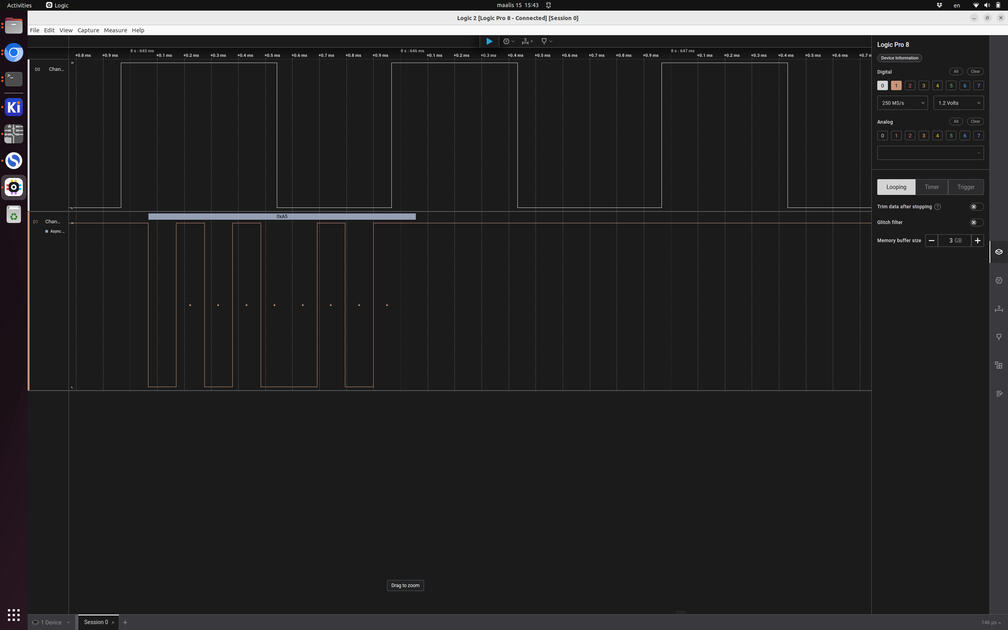
Screenshot of the UI of the software:
We also did order a programmer boards from the board house - made by Quentin Bolsee.